Difference between revisions of "PBX-USB"
From PROBOTIX :: wiki
(→Description) |
m |
||
| (17 intermediate revisions by the same user not shown) | |||
| Line 1: | Line 1: | ||
| − | [[ | + | [[Category:Breakout Boards]] |
| − | [[ | + | {{Depreciated}} |
| + | [[Image:PBX-USB.jpg|thumb|500px|PBX-USB]] | ||
| − | == Hardware Features | + | == Hardware Features == |
| − | + | * 4 axis USB CNC controller | |
| − | + | * USB (V2.x) from PC/Laptop running Windows XP, Vista or Windows 7(32 bit or 64 bit) | |
| − | + | * 3 digital outputs (flood, mist, spindle) | |
| − | + | * 25 KHz maximum step frequency | |
| − | + | * 12us minimum pulse width | |
| − | + | * Buffered I/O for maximum performance | |
| − | + | * Two manual jog input keys per axis (8 total) | |
| − | + | * Two limit switches each for X,Y, Z (6 total) | |
| − | + | * Jog Pendant Interface | |
| − | + | * Relay Board Interface | |
| − | + | * I2C Interface | |
| − | + | * E-Stop Loop | |
| − | + | ||
| − | + | ||
| − | + | ||
| − | + | ||
| − | + | ||
| − | + | ||
| − | + | ||
| − | + | ||
| − | + | ||
| − | + | ||
| − | + | ||
| + | == Software Features == | ||
| + | * Advanced interpolation algorithms | ||
| + | * Control external devices with I2C protocol | ||
| + | * Pause/resume of execution supported | ||
| + | * Automatic homing procedure | ||
| + | * Touch Plate Tool Change Procedure | ||
| + | * Standard RS274/NGC G-code (EMC2 compatible) | ||
| + | * Toolpath simulation | ||
| + | * Advanced G-codes - G40, G41, G42 (Cutter Radius Compensation) supported | ||
| + | * Advanced G-codes - G43, G49 (Tool Length Offsets) supported | ||
| + | * Advanced G-codes - G54, G59.3 (Coordinate System Origins) | ||
== Description == | == Description == | ||
| + | The PBX-USB is a USB interfaced CNC controller that was developed specifically to work with the CNC USB Motion Controller Software from [http://www.planet-cnc.com www.planet-cnc.com]. This Interface sports 4x 10 pin PBX-Header Connections for interfacing to our existing stepper motor drivers. It has an additional header for direct connection to our RBX-1 3 channel relay board. This software/hardware combination can be further expanded with jog key inputs and an I2C bus for nearly unlimited additional I/O. This will allow the development of jog pendants, digital readouts, and input/output cards for a variety of purposes. The software runs on Windows and replaces Mach3 or EMC2. It can even be run through a virtual machine on a Mac or Linux host. | ||
| − | + | == Diagram == | |
| − | + | [[Image:PBX-USB_diagram.jpg|600px]] | |
| − | + | [[Image:PBX-Header.jpg|thumb|250px|Figure 1: PBX Header]] | |
| + | [[Image:I2C-Header.jpg|thumb|250px|Figure 2: I2C Header]] | ||
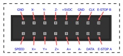
| + | [[Image:PENDANT_Header.jpg|thumb|250px|Figure 3: Pendant Header]] | ||
| − | == | + | == Technical Details == |
| − | + | {| cellpadding="10px" | |
| + | | align="right" | JP1 | ||
| + | |Vin - Powers micro-controller from 5V derived from Vin<br>Vusb - Power micro-controller from USB (recommended) | ||
| + | |- valign="top"; | ||
| + | | align="right" | POT | ||
| + | |Connect a 10K logarithmic taper potentiometer to control jog speed. This signal is replicated in the pendant header (SPEED). | ||
| + | |- | ||
| + | | align="right" | E-stop Loop | ||
| + | |The E-stop loop is a normally closed circuit which loops through the 16-pin pendant header and the e-stop loop screw terminals. Any open condition in the loop will cause an e-stop. If e-stop switch(es) are not used, the circuit must be closed with jumpers. A small peice of wire will suffice to close the screw terminal loop. | ||
| + | |- | ||
| + | | align="right" | Jog Inputs | ||
| + | |The jog inputs can be used to make a simple jog pendant. Normally open push buttons connected to the jog inputs and the adjacent +5V connections will do the trick. | ||
| + | |- | ||
| + | | align="right" | Limit/Home Inputs | ||
| + | |Normally closed limit/home switch loops. You can use a single input for both + and - switches, or separate switch inputs for + & -. The LZ- input is used for the tool length compensation touch plate. | ||
| + | |- | ||
| + | | align="right" | Aux Outputs | ||
| + | |The spindle, mist, and flood outputs come out to the relay board header for direct connection to our RBX-1 relay board. Those signals are also replicated to the screw terminals for connection to other devices. The signal output cannot exceed 20mA or the micro-controller will be damaged. | ||
| + | |- | ||
| + | | align="right" | I2C | ||
| + | |Currently the I2C interface suports Spindle (M3, M4, M5), Coolant (M7, M8, M9), general purpose outputs (M62, M63, M64, M65), as well as current machine position. | ||
| + | |} | ||
| − | + | == Notes == | |
| − | + | * Step and Direction are printed reversed on the PCB | |
| − | + | ||
| − | + | == Setting Files == | |
| − | + | The zip file contains both V90 and X90 settings. You will need to adjust these settings to match the performance of your machine setup. | |
| − | : | + | * [[File:V90_X90_Settings.zip]] |
Latest revision as of 09:29, 29 September 2018
Contents
Hardware Features
- 4 axis USB CNC controller
- USB (V2.x) from PC/Laptop running Windows XP, Vista or Windows 7(32 bit or 64 bit)
- 3 digital outputs (flood, mist, spindle)
- 25 KHz maximum step frequency
- 12us minimum pulse width
- Buffered I/O for maximum performance
- Two manual jog input keys per axis (8 total)
- Two limit switches each for X,Y, Z (6 total)
- Jog Pendant Interface
- Relay Board Interface
- I2C Interface
- E-Stop Loop
Software Features
- Advanced interpolation algorithms
- Control external devices with I2C protocol
- Pause/resume of execution supported
- Automatic homing procedure
- Touch Plate Tool Change Procedure
- Standard RS274/NGC G-code (EMC2 compatible)
- Toolpath simulation
- Advanced G-codes - G40, G41, G42 (Cutter Radius Compensation) supported
- Advanced G-codes - G43, G49 (Tool Length Offsets) supported
- Advanced G-codes - G54, G59.3 (Coordinate System Origins)
Description
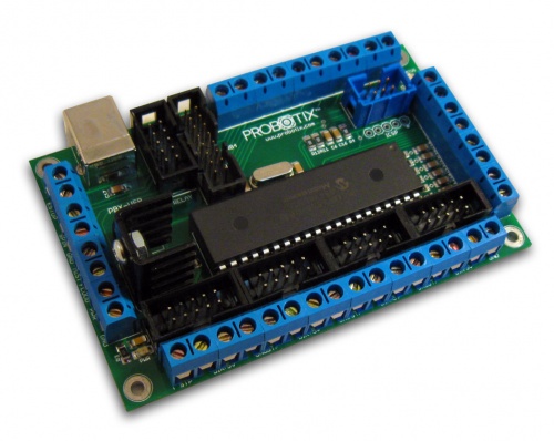
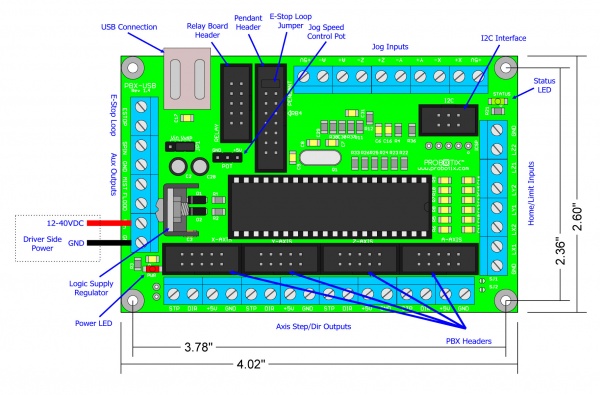
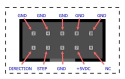
The PBX-USB is a USB interfaced CNC controller that was developed specifically to work with the CNC USB Motion Controller Software from www.planet-cnc.com. This Interface sports 4x 10 pin PBX-Header Connections for interfacing to our existing stepper motor drivers. It has an additional header for direct connection to our RBX-1 3 channel relay board. This software/hardware combination can be further expanded with jog key inputs and an I2C bus for nearly unlimited additional I/O. This will allow the development of jog pendants, digital readouts, and input/output cards for a variety of purposes. The software runs on Windows and replaces Mach3 or EMC2. It can even be run through a virtual machine on a Mac or Linux host.
Diagram
Technical Details
| JP1 | Vin - Powers micro-controller from 5V derived from Vin Vusb - Power micro-controller from USB (recommended) |
| POT | Connect a 10K logarithmic taper potentiometer to control jog speed. This signal is replicated in the pendant header (SPEED). |
| E-stop Loop | The E-stop loop is a normally closed circuit which loops through the 16-pin pendant header and the e-stop loop screw terminals. Any open condition in the loop will cause an e-stop. If e-stop switch(es) are not used, the circuit must be closed with jumpers. A small peice of wire will suffice to close the screw terminal loop. |
| Jog Inputs | The jog inputs can be used to make a simple jog pendant. Normally open push buttons connected to the jog inputs and the adjacent +5V connections will do the trick. |
| Limit/Home Inputs | Normally closed limit/home switch loops. You can use a single input for both + and - switches, or separate switch inputs for + & -. The LZ- input is used for the tool length compensation touch plate. |
| Aux Outputs | The spindle, mist, and flood outputs come out to the relay board header for direct connection to our RBX-1 relay board. Those signals are also replicated to the screw terminals for connection to other devices. The signal output cannot exceed 20mA or the micro-controller will be damaged. |
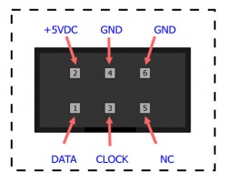
| I2C | Currently the I2C interface suports Spindle (M3, M4, M5), Coolant (M7, M8, M9), general purpose outputs (M62, M63, M64, M65), as well as current machine position. |
Notes
- Step and Direction are printed reversed on the PCB
Setting Files
The zip file contains both V90 and X90 settings. You will need to adjust these settings to match the performance of your machine setup.

