Difference between revisions of "Automatic Tool Length Sensor"
From PROBOTIX :: wiki
| Line 15: | Line 15: | ||
<code>o100 CALL [1]</code> | <code>o100 CALL [1]</code> | ||
| + | We will post modified post processors here on the wiki as we compile them. Please contact us if you need help modifying a post processor. | ||
---- | ---- | ||
| Line 61: | Line 62: | ||
</pre> | </pre> | ||
| − | |||
| − | |||
| − | |||
| − | |||
| − | |||
| − | |||
| − | |||
| − | |||
---- | ---- | ||
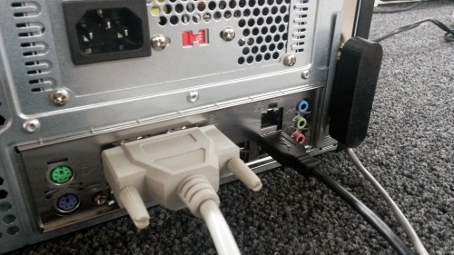
[[image:ATLaS_2.jpg|thumb|500px|ATLaS Connector]] | [[image:ATLaS_2.jpg|thumb|500px|ATLaS Connector]] | ||
The ATLaS automatic tool length sensor will plug into the secondary parallel port connector on the back of the control PC. | The ATLaS automatic tool length sensor will plug into the secondary parallel port connector on the back of the control PC. | ||
Revision as of 10:32, 5 September 2014
When using multiple tools on a CNC operation, the z-axis is always the goofy axis because, for instance, the lengths of the tools are all different and the distance the tool is inserted into the collet can vary widely - both intentionally and unintentionally. With conventional CNC routing, each tool operation has to be done in a separate g-code file, with each tool needing to be touched off in the z-axis on each tool change.
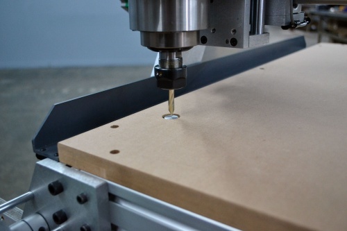
The new ATLaS automatic tool length sensor for the Comet/Asteroid/Meteor machines radically optimizes this tool change process. With the tool length sensor, you will touch off the first tool with the tool sensor, then touch that tool off to the top of the part to establish the z-axis origin. You will only have to touch off the top of the part one time. On each tool change, the machine will shut off the spindle and drive out to the front of the machine to allow for easy tool change access. The machine will then drive over until it is above the tool sensor, will bounce off of that sensor, will then continue with the cutting process using the new compensated tool length offset.
The tool sensor can measure tools up to 5/8" diameter. You can still use larger tools if you need, but you will not be able to use the automatic tool length sensor when you do. The sensor sits just below the surface of the spoil board. You can make use of that area of the table if you need, but again you will not be able to use the automatic tool length sensor when you do.
To use the this Automatic tool length sensor, your CAM post-processor will need to be modified such that the tool change function, which typically looks like this:
M6 T1
The new tool change function will look like this:
o100 CALL [1]
We will post modified post processors here on the wiki as we compile them. Please contact us if you need help modifying a post processor.
Here is the tool change routine. This file is named 100.ngc and must be kept in the nc_files directory.
o100 SUB

(#1 must be passed as tool number)
#30 = ROUND[#5220] (stores the current coordinate system)

M9
G59.3 (use G59.3 as zero location for touch sensor)
G53 G90 G0 Z0
G53 X12.5 Y0
T#1 M6
G0 X0 Y0
G91 G38.2 Z-5 F10
G10 L11 P#1 Z0 R0
G53 G90 G0 Z-.1
G43
G91 Z0.1
G90

(reset to the previous coordinate system)
o102 IF [#30 EQ 1]
  G54
o102 ELSEIF [#30 EQ 2]
  G55
o102 ELSEIF [#30 EQ 3]
  G56
o102 ELSEIF [#30 EQ 4]
  G57
o102 ELSEIF [#30 EQ 5]
  G58
o102 ELSEIF [#30 EQ 6]
  G59
o102 ELSEIF [#30 EQ 7]
  G59.1
o102 ELSEIF [#30 EQ 8]
  G59.2
o102 ENDIF

o100 ENDSUB
The ATLaS automatic tool length sensor will plug into the secondary parallel port connector on the back of the control PC.


