Difference between revisions of "Automatic Tool Length Sensor"
From PROBOTIX :: wiki
m (→Vectric CAM software: remove old directions) |
|||
| (25 intermediate revisions by the same user not shown) | |||
| Line 1: | Line 1: | ||
| − | [[ | + | [[File:ATLaS_1.jpg|thumb|ATLaS Automatic Tool Length Sensor]] |
| − | When | + | When purchasing a [[:Category:Galaxy Series|Galaxy]] or [[:Category:GX Series|GX]] series machine, you will have an option for PROBOTIX to install, configure and test this sensor before it ships. This page goes into detail about how to use the tool length sensor. If you do not choose to have the Automatic Tool Length Sensor (ATLaS) factory installed and instead purchase the sensor at a later date, you will need to start with the [[#Installation]] and [[#Configuration]] sections below. |
| − | + | == About == | |
| + | When using multiple tools on a CNC operation the Z-axis is always the goofy axis because, for instance, the lengths of the tools are all different and the distance the tool is inserted into the collet can vary widely - both intentionally and unintentionally. With conventional CNC routing each tool operation has to be done in a separate g-code file, with each tool needing to be touched-off in the Z-axis on each tool change. | ||
| − | The tool | + | The new ATLaS radically optimizes the tool change process. With the tool length sensor, you will load the first tool, then the machine will capture the tool length with the sensor before you touch that tool off to the top of the part. This will establish the Z-axis origin and you will only have to touch off the top of the part this one time. On each tool change, the machine will shut off the spindle and drive out to the front of the machine to allow for easy tool change access. The machine will then drive over until it is above the tool sensor, will bounce off of that sensor, will then continue with the cutting process using the new compensated tool length offset. |
| − | + | The tool sensor can measure tools up to 5/8" diameter. You can still use larger tools if you need, but you will not be able to use the ATLaS when you do as the sensor sits just below the surface of the spoil board. You can make use of that area of the table if you need, but again you will not be able to use the ATLaS. | |
| − | + | ||
| − | ::<code> | + | == Usage == |
| + | To use the ATLaS, your CAM post-processor will need to be modified such that the tool change function is no longer g-code M6. The tool change function typically looks like this: | ||
| + | |||
| + | :<code>T1 M6</code> | ||
The new tool change function will look like this: | The new tool change function will look like this: | ||
| − | + | :<code>o100 CALL [1]</code> | |
| − | + | The <code>o100</code> subroutine handles loading of the G43 tool length compensation, so if the post processor is inserting G43s, they will need to be removed as well. | |
| − | + | === Step-by-step === | |
| + | <gallery mode="packed-overlay"> | ||
| + | File:Estop.png|E-Stop | ||
| + | File:Loadfirsttool.png|Load First Tool | ||
| + | File:Inserttool1.png|Insert Tool 1 | ||
| + | File:Inserttool3.png|Insert Tool 3 | ||
| + | </gallery> | ||
| − | + | # Launch LinuxCNC | |
| + | # Toggle the eStop switch and make sure the red e-Stop indicator follows the position of the physical eStop switch. (see E Stop image) | ||
| + | # Activate the software by pressing the orange machine power button (or F2) | ||
| + | # Home the machine by clicking {{AxisButton|Home All}} or [[File:tool_home.gif]] | ||
| + | # Click the {{AxisButton|Load 1st Tool}} or {{AxisButton|Measure 1st Tool}} button. (see [[Probotix Axis Interface]]) | ||
| + | #* This will bring the spindle out to the front of the machine and prompt you to load Tool #1 | ||
| + | #* You don't have to actually use Tool #1, you may have another tool you prefer to do your touch-offs with, if so then load that tool. | ||
| + | # It will say "Insert tool 1 and click continue when ready." - do so. (see Insert Tool 1) | ||
| + | # The machine will drive over to the center of the tool sensor and plunge down. | ||
| + | #* Make sure to have your finger on the escape key in case it's plunging down in the wrong place and if so, see [[#Not centered over ATLaS]]. | ||
| + | # After it calculates the length of the tool it will raise all the way up, and then move over a small amount in the X (to prevent accidental crashes into the tool sensor). At the bottom of the screen you will see now "Tool 1" and the calculated length of the tool. | ||
| + | # Now if you go to the MDI screen, you will see that G43 is now listed in the list of active G-codes. This means that you are now operating in tool length compensation mode. A G49 will cancel tool length compensation mode if you need to go back to the traditional machine methods - ie: the way you did things before you installed the tool sensor. | ||
| + | # Now, mount your stock up on the table. Jog the machine over and touch off as you normally would. When touching off while G43 is active, the Z axis touch off is referenced to the length of the tool rather than the actual height of the stock. | ||
| + | # Now you are ready to run your program. In your program, whenever LinuxCNC encounters <code>o100 CALL [tool_number]</code> it will turn off the spindle, drive the spindle out to the front of the machine, and lift all the way up to give you easy access to changing the tool. A dialog box will pop up on the screen prompting you to load the next tool. To be safe, you may want to turn off the physical power button on the side of your router if it has one. Don't forget to turn it back on or else you may drag the tool through your part. | ||
| + | # After you click continue, it will drive over and measure the length of the new tool and continue with the next cutting operation. | ||
| − | + | <div class="warningbox">'''IMPORTANT:''' If you change your spindle/spindle mount, the Y position may be different and you may need to adjust the ATLaS position as noted [[#Not centered over ATLaS| below]].</div> | |
| − | + | == Post Processors == | |
| + | We will post modified post processors here on the wiki as we compile them. | ||
| − | + | === Vectric CAM software === | |
| − | + | * [[Media:PROBOTIX_LinuxCNC_ATLaS_G64_Arc_Inch_TTS.zip]] | |
| + | * Then move that file into the PostP folder on your PC. | ||
| − | + | === Where to find the Post Processors directory on your PC === | |
| − | + | * http://support.vectric.com/aspire-questions/item/where-to-find-post-processors-folder-on-pc | |
| + | * http://forum.vectric.com/viewtopic.php?f=4&t=6213 | ||
| − | + | == Installation == | |
| − | + | [[image:ATLaS_2.jpg|thumb|ATLaS Connector]] | |
| − | + | The ATLaS will plug into the secondary parallel port connector on the back of the control PC. If your ATLaS was not factory installed you will need to [[LinuxCNC Configurator| re-configure]] your machine for its usage. | |
| − | + | ||
| − | + | ||
| − | + | ||
| − | + | ||
| − | + | ||
| − | + | ||
| − | + | ||
| − | + | ||
| − | + | ||
| − | + | === Retrofitting an Existing Machine === | |
| − | + | You can mount the ATLaS anywhere on the machine that the tool can reach but if you purchased the machine in 2015 or later it will already have a hole in the spoil board for mounting in the left hand corner closest to the front of the machine. Otherwise you will need to drill a 3/4" hole in the spoil board that the plunger will fit through. If you are going to remove your spoil board to do this see [[Spoil_Boards#Installing/Removing the Spoilboard|Installing/Removing the Spoilboard]]. | |
| − | + | ||
| − | + | ||
| − | + | ||
| − | + | ||
| − | + | ||
| − | + | ||
| − | + | ||
| − | + | ||
| − | + | ||
| − | + | ||
| − | + | ||
| − | + | ||
| − | + | ||
| − | + | ||
| − | + | ||
| − | + | ||
| − | + | If you purchased the ATLaS separately it may come with a DB25 connector to be used on the secondary parallel port on the PC. If you already have a Z-puck installed with a DB25 connector of its own see [[Z Touch-off Puck#Retrofitting an Existing Machine|Z-puck Retrofitting]] | |
| − | </ | + | <div class="warningbox">'''IMPORTANT:''' If you choose to mount the sensor anywhere other than the location that we provided, then you will need to modify your <code>100.ngc</code> file manually as the location of the sensor is hard-coded in that file now.</div> |
| − | + | === Configuration === | |
| − | [[ | + | You will need to reconfigure LinuxCNC for your machine to make use of the tool sensor. Follow the configuration instructions here: [[LinuxCNC Configurator]] |
| − | The | + | * The new configuration will place a Probe LED on the right hand panel of the screen. Depress the plunger on the probe and make sure the indicator responds before proceeding. |
| + | == Code == | ||
| − | + | Below is the tool change routine and must be kept in the <code>/nc_files</code> directory and be named <code>100.ngc</code> | |
| − | + | ||
| − | + | <pre> | |
| + | o100 SUB | ||
| − | + | (#1 tool number as passed from CALL) | |
| − | + | #<_ATLAS_X> = -0.075 (Absolute machine X position for tool sensor) | |
| + | #<_ATLAS_Y> = 3.5533 (Absolute machine Y position for tool sensor) | ||
| + | #<_MULTIPLIER> = 1 (1 for INCH, 25.4 for MM) | ||
| + | #<_Z_MIN> = 5 (maximum Z- probe search distance) | ||
| + | #<_X_PARK> = REPLACE_X_PARK | ||
| − | + | M5 M9 (turn off spindle and shop vac) | |
| − | + | REPLACE_GUNITS (set units) | |
| − | + | G53 G90 G0 Z0 (retract z) | |
| − | + | (#5400 is current tool number) | |
| − | + | o101 if [#1 NE #5400] (if tool number has changed) | |
| + | G53 G0 X#<_X_PARK> Y0 (drive out to front of machine) | ||
| + | T#1 M6 (tool change prompt) | ||
| + | o101 endif | ||
| − | + | G53 G0 X#<_ATLAS_X> Y#<_ATLAS_Y> (move over tool sensor) | |
| − | 2 | + | G91 G38.2 Z-#<_Z_MIN> F[10 * #<_MULTIPLIER>] (feed down until probe is active) |
| − | + | G10 L11 P#1 Z0 R0 (set tool table) | |
| + | G53 G90 G0 Z0 (retract most of the way up) | ||
| + | G43 (load tool length offset for current tool) | ||
| + | G91 X[2 * #<_MULTIPLIER>] (move over 2 inches to right) | ||
| + | G90 (jump back into absolute mode) | ||
| − | + | o100 ENDSUB | |
| − | + | </pre> | |
| − | + | ||
| − | + | ||
| − | + | ||
| − | + | ||
| − | + | ||
| − | + | ||
| − | + | ||
| − | + | ||
| − | + | ||
| − | + | ||
| − | + | ||
| − | + | ||
| − | + | ||
| − | + | ||
| − | + | ||
| − | + | ||
| − | + | ||
| − | + | ||
| − | + | ||
| − | + | ||
| − | + | ||
| − | + | ||
| − | + | ||
| − | + | ||
| − | + | ||
| − | + | ||
| − | + | ||
| − | + | ||
| − | + | ||
| − | + | ||
| − | + | ||
| − | + | ||
| − | + | ||
| − | + | ||
| − | + | ||
| − | + | ||
| − | + | ||
| − | + | ||
| − | + | ||
| − | + | ||
| − | + | ||
| − | + | ||
| − | + | ||
| − | + | ||
| − | + | ||
| − | + | ||
| − | + | ||
| − | + | ||
| − | + | ||
| − | + | ||
| − | + | ||
| − | + | ||
| − | + | ||
| − | + | ||
| − | + | ||
| − | + | ||
| − | + | ||
| − | + | ||
| − | + | ||
| − | + | ||
| − | + | ||
| − | + | ||
| − | + | ||
| − | + | == FAQ == | |
| + | === Not centered over ATLaS === | ||
| + | If your spindle/router does not center over the ATLaS sensor before plunging down you may need to adjust the Y-coordinate of the ATLaS location. | ||
| + | # Start by positioning the machine over the ATLaS button in order to determine the Y-coordinate. | ||
| + | # Open the <code>100.ngc</code> file located in <code>/nc_files/subs</code> | ||
| + | # Edit the line <code>#<_ATLAS_Y></code> to equal the Y location you previously found. | ||
| + | # Don't forget to save the <code>100.ngc</code> file for the change to take place. | ||
Latest revision as of 09:36, 22 January 2019

When purchasing a Galaxy or GX series machine, you will have an option for PROBOTIX to install, configure and test this sensor before it ships. This page goes into detail about how to use the tool length sensor. If you do not choose to have the Automatic Tool Length Sensor (ATLaS) factory installed and instead purchase the sensor at a later date, you will need to start with the #Installation and #Configuration sections below.
Contents
About
When using multiple tools on a CNC operation the Z-axis is always the goofy axis because, for instance, the lengths of the tools are all different and the distance the tool is inserted into the collet can vary widely - both intentionally and unintentionally. With conventional CNC routing each tool operation has to be done in a separate g-code file, with each tool needing to be touched-off in the Z-axis on each tool change.
The new ATLaS radically optimizes the tool change process. With the tool length sensor, you will load the first tool, then the machine will capture the tool length with the sensor before you touch that tool off to the top of the part. This will establish the Z-axis origin and you will only have to touch off the top of the part this one time. On each tool change, the machine will shut off the spindle and drive out to the front of the machine to allow for easy tool change access. The machine will then drive over until it is above the tool sensor, will bounce off of that sensor, will then continue with the cutting process using the new compensated tool length offset.
The tool sensor can measure tools up to 5/8" diameter. You can still use larger tools if you need, but you will not be able to use the ATLaS when you do as the sensor sits just below the surface of the spoil board. You can make use of that area of the table if you need, but again you will not be able to use the ATLaS.
Usage
To use the ATLaS, your CAM post-processor will need to be modified such that the tool change function is no longer g-code M6. The tool change function typically looks like this:
T1 M6
The new tool change function will look like this:
o100 CALL [1]
The o100 subroutine handles loading of the G43 tool length compensation, so if the post processor is inserting G43s, they will need to be removed as well.
Step-by-step
E-Stop
Load First Tool

Insert Tool 1
Insert Tool 3


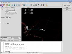
- Launch LinuxCNC
- Toggle the eStop switch and make sure the red e-Stop indicator follows the position of the physical eStop switch. (see E Stop image)
- Activate the software by pressing the orange machine power button (or F2)
- Home the machine by clicking Home All or

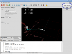
- Click the Load 1st Tool or Measure 1st Tool button. (see Probotix Axis Interface)
- This will bring the spindle out to the front of the machine and prompt you to load Tool #1
- You don't have to actually use Tool #1, you may have another tool you prefer to do your touch-offs with, if so then load that tool.
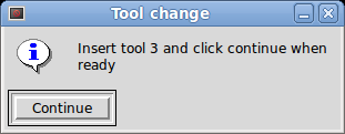
- It will say "Insert tool 1 and click continue when ready." - do so. (see Insert Tool 1)
- The machine will drive over to the center of the tool sensor and plunge down.
- Make sure to have your finger on the escape key in case it's plunging down in the wrong place and if so, see #Not centered over ATLaS.
- After it calculates the length of the tool it will raise all the way up, and then move over a small amount in the X (to prevent accidental crashes into the tool sensor). At the bottom of the screen you will see now "Tool 1" and the calculated length of the tool.
- Now if you go to the MDI screen, you will see that G43 is now listed in the list of active G-codes. This means that you are now operating in tool length compensation mode. A G49 will cancel tool length compensation mode if you need to go back to the traditional machine methods - ie: the way you did things before you installed the tool sensor.
- Now, mount your stock up on the table. Jog the machine over and touch off as you normally would. When touching off while G43 is active, the Z axis touch off is referenced to the length of the tool rather than the actual height of the stock.
- Now you are ready to run your program. In your program, whenever LinuxCNC encounters
o100 CALL [tool_number]it will turn off the spindle, drive the spindle out to the front of the machine, and lift all the way up to give you easy access to changing the tool. A dialog box will pop up on the screen prompting you to load the next tool. To be safe, you may want to turn off the physical power button on the side of your router if it has one. Don't forget to turn it back on or else you may drag the tool through your part. - After you click continue, it will drive over and measure the length of the new tool and continue with the next cutting operation.
Post Processors
We will post modified post processors here on the wiki as we compile them.
Vectric CAM software
- Media:PROBOTIX_LinuxCNC_ATLaS_G64_Arc_Inch_TTS.zip
- Then move that file into the PostP folder on your PC.
Where to find the Post Processors directory on your PC
- http://support.vectric.com/aspire-questions/item/where-to-find-post-processors-folder-on-pc
- http://forum.vectric.com/viewtopic.php?f=4&t=6213
Installation

The ATLaS will plug into the secondary parallel port connector on the back of the control PC. If your ATLaS was not factory installed you will need to re-configure your machine for its usage.
Retrofitting an Existing Machine
You can mount the ATLaS anywhere on the machine that the tool can reach but if you purchased the machine in 2015 or later it will already have a hole in the spoil board for mounting in the left hand corner closest to the front of the machine. Otherwise you will need to drill a 3/4" hole in the spoil board that the plunger will fit through. If you are going to remove your spoil board to do this see Installing/Removing the Spoilboard.
If you purchased the ATLaS separately it may come with a DB25 connector to be used on the secondary parallel port on the PC. If you already have a Z-puck installed with a DB25 connector of its own see Z-puck Retrofitting
100.ngc file manually as the location of the sensor is hard-coded in that file now.Configuration
You will need to reconfigure LinuxCNC for your machine to make use of the tool sensor. Follow the configuration instructions here: LinuxCNC Configurator
- The new configuration will place a Probe LED on the right hand panel of the screen. Depress the plunger on the probe and make sure the indicator responds before proceeding.
Code
Below is the tool change routine and must be kept in the /nc_files directory and be named 100.ngc
o100 SUB

(#1 tool number as passed from CALL)
#<_ATLAS_X> = -0.075                            (Absolute machine X position for tool sensor)
#<_ATLAS_Y> = 3.5533                            (Absolute machine Y position for tool sensor)
#<_MULTIPLIER> = 1                              (1 for INCH, 25.4 for MM)
#<_Z_MIN> = 5                                   (maximum Z- probe search distance)
#<_X_PARK> = REPLACE_X_PARK

M5 M9						(turn off spindle and shop vac)
REPLACE_GUNITS					(set units)
G53 G90 G0 Z0 					(retract z)

(#5400 is current tool number)
o101 if [#1 NE #5400] 				(if tool number has changed)
	G53 G0 X#<_X_PARK> Y0			(drive out to front of machine)
	T#1 M6 					(tool change prompt)
o101 endif

G53 G0 X#<_ATLAS_X> Y#<_ATLAS_Y>		(move over tool sensor)
G91 G38.2 Z-#<_Z_MIN> F[10 * #<_MULTIPLIER>]	(feed down until probe is active)
G10 L11 P#1 Z0 R0				(set tool table)
G53 G90 G0 Z0			                (retract most of the way up)
G43                                             (load tool length offset for current tool)
G91 X[2 * #<_MULTIPLIER>]			(move over 2 inches to right)
G90						(jump back into absolute mode)

o100 ENDSUB
FAQ
Not centered over ATLaS
If your spindle/router does not center over the ATLaS sensor before plunging down you may need to adjust the Y-coordinate of the ATLaS location.
- Start by positioning the machine over the ATLaS button in order to determine the Y-coordinate.
- Open the
100.ngcfile located in/nc_files/subs - Edit the line
#<_ATLAS_Y>to equal the Y location you previously found. - Don't forget to save the
100.ngcfile for the change to take place.