Difference between revisions of "PBX-BB rev5.2"
From PROBOTIX :: wiki
| (30 intermediate revisions by the same user not shown) | |||
| Line 1: | Line 1: | ||
| − | + | Previous Rev: [[PBX-BB_rev4.1]] | |
<hr> | <hr> | ||
| − | |||
[[category:Breakout Boards]] | [[category:Breakout Boards]] | ||
| − | |||
| − | |||
| − | |||
Model: PBX-BB BeagleBone Breakout Board | Model: PBX-BB BeagleBone Breakout Board | ||
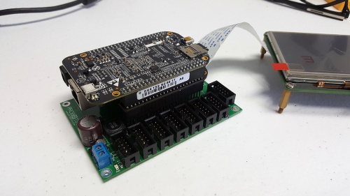
| − | + | [[image:PBX-BB_rev5.1_image1.jpg|thumb|500px|PBX-BB rev5.1]] | |
| − | :* | + | == Specs: == |
| − | + | ||
| − | + | * BeagleBone Black Compatible | |
| − | + | * 6x PBX-Headers | |
| − | + | * Isolated Inputs and Outputs | |
| − | + | * 16 Outputs and 8 Inputs | |
| + | * Integrated 5V/2A Logic Supply Regulator | ||
| + | * USB Powered BeagleBone | ||
== Description: == | == Description: == | ||
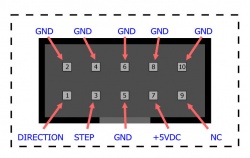
| − | + | [[image:PBX-Header.jpg|thumb|250px|Figure 1: PBX Header]] | |
| − | + | ||
| − | The PBX-BB | + | The PBX-BB rev5.2 is our newest breakout board for the [[BeagleBone]]. It was designed to work with the LinuxCNC derivative, [http://www.machinekit.io Machinekit]. It features 16 total outputs and 8 inputs, all software mappable to whichever signals you need. The PBX-BB rev5.1 was redesigned to address pin conflicts that prevented the use of the direct LCD control built into the Beaglebone. You can now piggy back many of the popular LCD panels, such as the LCD4 and LCD7 capes from 4D Systems, as well as the BB-View capes from Element 14. |
| − | + | The PBX-BB has 6x PBX-Headers (Figure 1) for easy connections to our stepper drivers and relay boards. Input signals now make use of 10 pin IDC headers as well. | |
| − | + | ||
| − | + | The PBX-BB rev5.2 keeps the tried and true MAX5090 based 5V/2A switching regulator that accepts voltages up to 76VDC. The 5V rail is bused out to the PBX-Headers just like our other breakout boards, allowing you to drive the logic supply of the drivers from a single power source. | |
| − | + | ||
| − | + | ||
| − | + | ||
| − | + | ||
| − | + | ||
== Getting Started == | == Getting Started == | ||
| − | |||
| − | |||
| − | |||
| − | |||
| − | |||
| − | |||
| − | |||
| − | |||
| − | |||
| − | == | + | # Download Machinekit Image from here: |
| − | + | #* https://elinux.org/Beagleboard:BeagleBoneBlack_Debian#BBW.2FBBB_.28All_Revs.29_Machinekit | |
| + | # Unzip using 7zip | ||
| + | #* 7zip: http://www.7-zip.org/download.html | ||
| + | # Write Image to 8GB MicroSD card using an image burning software: | ||
| + | #* Win32DiscImager: https://sourceforge.net/projects/win32diskimager/ | ||
| + | #* Rufus: https://rufus.akeo.ie/ | ||
| + | |||
| + | == Schematic == | ||
| + | |||
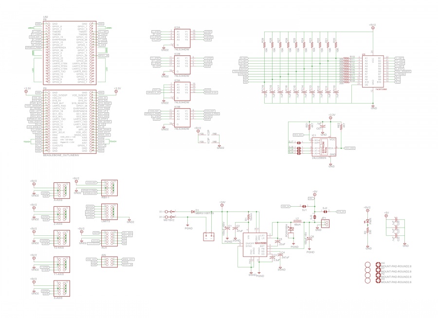
| + | [[image:PBX-BB_rev5.2_schematic.jpg|900px]] | ||
| + | |||
| + | == Manual == | ||
| + | |||
| + | [[Media:PBX-BB_rev5.2.pdf|PBX-BB rev5.2 manual]] | ||
| + | |||
| + | == Helpful Links == | ||
| − | + | * http://www.machinekit.io | |
| + | * http://www.machinekit.io/docs/ | ||
| + | * http://elinux.org/Beagleboard:BeagleBoneBlack_Debian#BBW.2FBBB_.28All_Revs.29_Machinekit | ||
| − | == | + | === Developers === |
| − | + | Cape EEPROMs: http://papermint-designs.com/community/node/331 | |
Latest revision as of 09:21, 12 March 2020
Previous Rev: PBX-BB_rev4.1
Model: PBX-BB BeagleBone Breakout Board
Contents
Specs:
- BeagleBone Black Compatible
- 6x PBX-Headers
- Isolated Inputs and Outputs
- 16 Outputs and 8 Inputs
- Integrated 5V/2A Logic Supply Regulator
- USB Powered BeagleBone
Description:
The PBX-BB rev5.2 is our newest breakout board for the BeagleBone. It was designed to work with the LinuxCNC derivative, Machinekit. It features 16 total outputs and 8 inputs, all software mappable to whichever signals you need. The PBX-BB rev5.1 was redesigned to address pin conflicts that prevented the use of the direct LCD control built into the Beaglebone. You can now piggy back many of the popular LCD panels, such as the LCD4 and LCD7 capes from 4D Systems, as well as the BB-View capes from Element 14.
The PBX-BB has 6x PBX-Headers (Figure 1) for easy connections to our stepper drivers and relay boards. Input signals now make use of 10 pin IDC headers as well.
The PBX-BB rev5.2 keeps the tried and true MAX5090 based 5V/2A switching regulator that accepts voltages up to 76VDC. The 5V rail is bused out to the PBX-Headers just like our other breakout boards, allowing you to drive the logic supply of the drivers from a single power source.
Getting Started
- Download Machinekit Image from here:
- Unzip using 7zip
- Write Image to 8GB MicroSD card using an image burning software:
- Win32DiscImager: https://sourceforge.net/projects/win32diskimager/
- Rufus: https://rufus.akeo.ie/
Schematic
Manual
Helpful Links
- http://www.machinekit.io
- http://www.machinekit.io/docs/
- http://elinux.org/Beagleboard:BeagleBoneBlack_Debian#BBW.2FBBB_.28All_Revs.29_Machinekit
Developers
Cape EEPROMs: http://papermint-designs.com/community/node/331


