CNC SOFTWARE
The fall-out of the DOT-COM bust has brought CNC to the hobbyist. Couple the availability of low/no cost CNC control software, low-cost integrated circuitry, and the tons of high-end hardware now found on eBay: and for the first time in history, CNC is attainable to the hobby market.
We prefer LinuxCNC (formerly EMC2) on Linux and Ubuntu, but there are others available for those who are shy.
- KCAM works great in Windows 98.
- Mach3 has a HUGE support group and bypasses some of the timing issues of the Windows environment.
- TurboCNC is a great piece of software, if you don't want to visualize your tool paths in real time and are comfortable in DOS.
LinuxCNC is completely Open Source, free to use, and probably the most reliable, flexible, robust system out there. The AXIS Graphical User Interface is second to none (IMHO).
The experts out there may disagree, but if you had to be an expert to do this.. you probably wouldn't be here right now, would you?
So, what software is involved in CNC? There are primarily three parts:
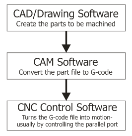 Your CAD (Computer Aided Design) software (wikipedia) is where you design your parts to be routed, lathed, milled, or cut.
CAM (Computer Aided Manufacturing) software (wikipedia) converts your CAD drawings into G-code, which is the programming language that the CNC control software understands.
The CNC control software then reads the G-code and turns it into motion to drive your machine. This is usually done by reading and writing pins on the parallel port, but there are some motor controllers which can operate from serial or USB, as well.
Our stepper motor driver kits make use of the parallel port signals. The breakout board splits these signals so that the step, direction, and enable lines for each axis are routed to each motor driver board.
There are other more specialized g-code generating tools used for specific purposes, such as generating PCB isolation routing, generating a pattern of holes, or roughing out a pocket. Some people choose to write the g-code by hand, as well.
Another type of CNC control software is available for specialized CNC hot-wire foam cutting machines.
CAD Software:
CAM Software:
| CNC Control Software (Machining/Milling/Lathe):
CNC Foam Cutting Software: CNC Utilities:
|
Parallel Port Interfacing:
Electronics CAD:
EagleCAD - PCB schematic and board layout program with free trial version
PCB-GCODE - a free g-code output for Eagle
Eagle3D - Render 3D images from EagleCad & POVRAY
CopperCAM - PCB Trace Isolation CAM
Useful Stuff:
IPM = (Frequency * 60) / (TPI * Steps Per Revolution * Microsteps)
Parallel ports need to run in EPP mode for any of the parallel port control software.
Configuring software steps per unit:
This variable stores how many steps to take to move the X axis 1 inch. You will need to set this as accurately as possible if you want your machine to be accurate. There are two ways to set it:
- Move and Measure - slap a pen or marker on as a tool head and draw a 1000 step line. Measure it and divide 1000 by the length in inches.
- Calculate Step Size - this one is the preferred way of doing things. Its rather easy to calculate step size based on your drive mechanism.
For threaded rod type drive systems:
Find your TPI (threads per inch). for example, 1/4"-20 threaded rod means that there are 20 threads per inch (aka 20 turns = 1 inch.) Simply take that number and multiply it by the steps in a revolution. With a 400 step motor (200 steps per revolution at half step), it would be 8000 steps per inch.
For belt/pulley systems:
- Find the circumference of your drive pulley. (remember circumference = 2*pi*r) (say: 2.75")
- Calculate step size (ie: circumference / steps per revolution) (say: 2.75" / 400 = 0.00625")
- Divide 1 inch by step size (1" / 0.00625" = 160 steps/inch)